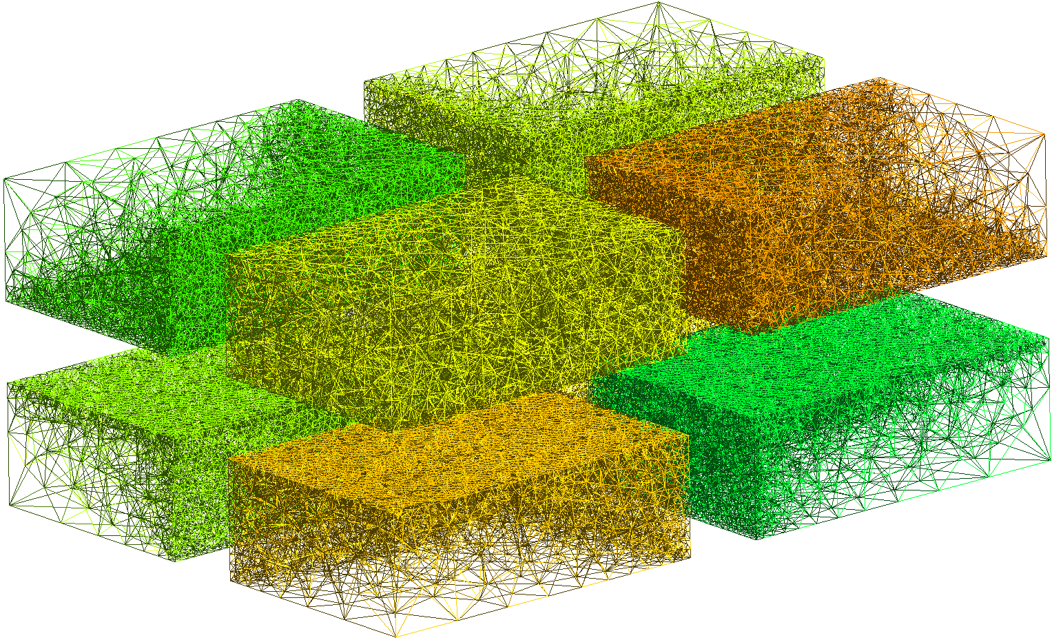
Dialog box for mesh exportingįollowing formats can be used for exporting.

If the mesh has no problem, select it in the model tree and export it with "Export mesh". Now you can see the generated mesh clearly. Then select - in menu bar to set 3D view wireframe display mode. step) and Iges formats Or returns a surface mesh from 3D volume mesh using.

Volume mesh in gmsh series#
Select the meshed solid on model tree and type space key to hide it. A model in Gmsh is defined using its Boundary Representation (BRep): a volume is bounded by a set of surfaces, a surface is bounded by a series of curves, and a. Returns a surface mesh from CAD model in Open Cascade Breap (.brep), Step (.stp or. Set paramters in the dialog box and click OK to create mesh. Max element size=0 (=Auto) Meshing=Automatic The angle threshold used to divide surfaces. The smaller the size, the finer the mesh. Meshing method (Adaptive, Delaunay, etc.).
Volume mesh in gmsh download#
Set the of the dialog box to the executable file in the FreeCAD installation folder (for example, "C:¥Program Files¥FreeCAD 0.19¥bin¥gmsh.exe" by default on Windows) or the executable file downloaded from the Gmsh download site. Whether meshes will be arranged like hexahedral.Įnable second order elements Enable quad dominantįor gmsh mesher, you should specify the Gmsh executable to be used at first. Whether second order elments will be generated. Whether optimization of surface shape will be done. If this parameter is larger, meshes becomes finer. If this parameter is smaller, meshes becomes finer. If you want to customize parameters, select "User defined". Maximum Edge length=10.0 Maximum Edge length=5.0 Maximum Edge length=2.0ĭegree of mesh fineness. Surface deviation=0.1 Surface deviation=0.01 Set segments to meshes depending on shape colors. Meshes to be created and the parameters of each mesher are as follow. Mesher that can be used are "Standard", "Mefisto", "Netgen" and "gmsh". Then select the mesher in the tabs of the dialog box and set each parameter. Select the shape in model tree and run "Mesh from shape" to show a dialog box as following. Switch workbench to Mesh Design wrokbench. There’s a birthday cake emoji appearing beside your username today.Create new document and create a shape to be meshed. To read the mesh, use from fenics import * This will give you two files, one containing the domain markers and one containing the surface markers. (Note that, because we will be producing a volume mesh instead of a surface mesh.
Volume mesh in gmsh code#
I’ll present my GMSH code below, but if a user has an idea that would satisfy my requirements without feeling the need to get into the weeds here, I’d be happy to try it. We begin by creating a gmsh geometry file for a sphere: ( Sphere.geo ).

In 3D, I presumed a Volume within a Volume would work the same way. In 2D problems, I have little trouble getting a method like this working by creating Surfaces within Surfaces, and specifying mesh widths as I please. My goal is to create a unit cube mesh with tight discretizations near the six faces, which relax to a coarser discretization as you move further away. (When I use a UnitCubeMesh my code works just fine.) I’m having some difficulty getting linear systems to converge (or simply be accepted as valid) in a mixed FE space when I use a mesh I’ve created in GMSH. From the mesh option, I changed the element size factor to create finer mesh, e.g I used element size factor 0.05, 0.03, and 0.01.


 0 kommentar(er)
